The Siamese Port Injection Problem
The fuel injection computer for conventional engines, ie with one port per cylinder, simply will not work on a siamese port engine. For basic batch fire systems it doesn’t matter whether the charge goes down an open valve or into the port where it waits for the valve to open up next time around or even when it happens. For engines with siamese inlet ports, eg BMC A and B series engines, it matters. A lot.
Let’s look at the firing order on these engines: 1-3-4-2 or, because it is cyclic it can be presented as 2-1 3-4. Look carefully at that grouping: the cylinders that share the inlet port fire after each other and they do so with the inside cylinder, 2 or 3, leading the outside cylinder 1 or 4. Now, stand in the 1-2 inlet port and watch what goes on as the engine runs. What the port sees is (in strokes): suck, suck, wait, wait. This is best shown on the polar graph I use for setting up camshafts on my engines. Instead of inlet and exhaust for # 1 cylinder, I’ve plotted the inlet valve motion for the outside and inside cylinders together. The timing is for a Kent 266 cam with standard 1.37:1 pressed steel rockers.
Can you see what’s going on? 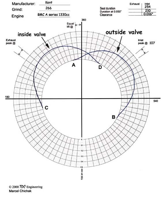
![]() from A to B the outside cylinder is sucking,
from A to B the outside cylinder is sucking,
![]() from C to D the inside cylinder is sucking and
from C to D the inside cylinder is sucking and
![]() between A and D they share the port.
between A and D they share the port.
Granted there’s not a lot of flow below 0.050” lift, but with a good exhaust system the opening valve will have a bit of extractor effect to carry mixture in and the closing valve will have a bit of gas inertia to continue drawing until the valve seats. The important thing to notice here is that any fuel deposited in the port after the outside valve closes, point B, will go to the inside valve. This means that:
![]() the inside valve takes anything injected into
the port from B to A which is 450° of the
720° port cycle or 63%,
the inside valve takes anything injected into
the port from B to A which is 450° of the
720° port cycle or 63%,
![]() the outside gets what’s injected between D and B
which is 180° or 25% and,
the outside gets what’s injected between D and B
which is 180° or 25% and,
![]() they share between A and D which is 90° or 12%.
they share between A and D which is 90° or 12%.
Setting fuel injection aside for the moment it’s obvious why carbureted engines always run with the outside cylinders leaner than the inside. Also, because lean mixtures burn faster and can tolerate less ignition advance than stoichiometric mixtures, on siamese port engines the outside cylinders are the first to knock and dictate the ignition curve while the inside cylinders have to run a bit retarded. If the engine had balanced cylinders it could run a touch more advance and would produce more power.
Using a batch injection ECU from a conventional engine but using one injector per port, which is all you really have room for, would result in a very poor running engine. Looking back at the polar diagram you can see that no matter where the ECU injects it is the first valve to open that gets the fuel. With the inside cylinder hogging 63% of the action you can see that the engine would likely run on 2 cylinders until the map nears saturation and even then the outside cylinders would still run lean.
So, how to solve this problem, knowing that it can be done because Rover produced the MPI Mini? Well, aside from throwing up your hands and going for an 8-port head, welding a wall down the middle of the ports, or simply using throttle body injection, you could have a new crank and cam made that would change the firing order to 1-3 2-4, but the cost? I’d love to try that!
But there’s another way. Look again at the polar plot. What the port is seeing is very much like a 2-stroke engine, ie, one induction per crank revolution except it’s not always happening at the same time in the 360° cycle. One happens at the beginning of the stroke while the second happens at the end. To solve the siamese port problem we have to get around unbalanced port sharing and that means that all the fuel for the outside cylinder must go down the open valve and that exact same amount of fuel must be fed to the inside cylinder which ever way it will take it. As stated above, there are millions of batch injected production engines where some cylinders get the fuel down the open valve and others get it deposited in the port and it just doesn’t matter.
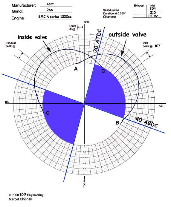
The thing missing from the polar plot is a time domain. This plot shows the amount of time the crank takes to go around 1 revolution or 360° and the amount of that revolution that a valve is open as seen from the siamese port. To avoid charge stealing by the inside cylinder the injector on-time must be less than the valve-open time. How much less? Well, the flow potential of a valve is not very great at 0.050” lift so that’s a good starting point. There’s also physical limits to consider like injector reaction time and travel time of the fuel charge from the injector tip to the back of the valve. The travel time is dictated by gas speed in the inlet port, which of course varies with VE and engine speed. I’ve estimated the travel time here. The next figure shows the start when the inside valve is 0.050” from the seat leaving an injection ‘window’ of 210°, or 58% of a revolution.
 Unfortunately
as engine speed increases fuel demand goes up so the injection window and
demand are converging. The critical
point will be at WOT and high engine speed. Adding the load domain to the
figure above which I have done in in the next figure, can create a fuel map
‘ceiling’. For the engine to run with inside and outside cylinders balanced,
the fuel map has to be below that ceiling.
Unfortunately
as engine speed increases fuel demand goes up so the injection window and
demand are converging. The critical
point will be at WOT and high engine speed. Adding the load domain to the
figure above which I have done in in the next figure, can create a fuel map
‘ceiling’. For the engine to run with inside and outside cylinders balanced,
the fuel map has to be below that ceiling.
Choosing the injector for a siamese port is critical. It needs to be big enough to get all the charge into one cylinder in one shot in less than 58% duty cycle and yet be small enough to be controlled during idle. If it’s too big the engine and won’t idle properly and produce high emissions, too small and the outer cylinders will run lean. If we knew what size the injectors are on the Rover TPI engine I wouldn’t have to take incredibly bold leaps to figure out the injector size to start with. However, since no one has shared that information, watch me go over this cliff here.
Setting the engine up will involve:
![]() having oxygen sensors in both the center branch
and an outside branch of the exhaust manifold to confirm balanced running,
having oxygen sensors in both the center branch
and an outside branch of the exhaust manifold to confirm balanced running,
![]() measuring the oxygen sensor outputs with a DVM
while running the computer open loop and adjusting the fuel map manually,
measuring the oxygen sensor outputs with a DVM
while running the computer open loop and adjusting the fuel map manually,
![]() an oscilloscope to confirm that the crank sensor
is indicating TDC correctly and the injectors are firing 30° ATDC,
an oscilloscope to confirm that the crank sensor
is indicating TDC correctly and the injectors are firing 30° ATDC,
![]() a reference chart to ensure injector on-times
are within the available ‘window’
a reference chart to ensure injector on-times
are within the available ‘window’
![]() a selection of injectors to zero in on the 58%
duty cycle.
a selection of injectors to zero in on the 58%
duty cycle.
Dyno testing will be needed to confirm both the 30° ATDC and 58% figures. Maybe the travel time from the injector tips to the cylinder is longer than I guessed and the injector can be fired earlier thereby making the window bigger and necessitating a smaller injector. Maybe shutting the injector off as the valve is closing is too late? Only testing and checking the oxygen sensors will tell.
Marcel Chichak
August, 2001